
|
||
|
User-Interface Design A good user-interface is an essential element of every application that requires even a minimum of interaction between user and computer. As such, a user-interface must be "intelligent" enough to perceive the requirements of a user depending on the current situation and the application specific context. While providing the right tools to the right time and such leading the user to the application procedure the user interface has to be non-obtrusive, because it must support, but not interfere with the user’s flow of thoughts. Hence, the ideal user-interface is simple, intuitive, and it adapts itself depending on the context. This simplicity comes, however, at a price: The simpler and more intuitive a user-interface gets, the more complex and difficult is its implementation.
|
|
|
|
The user-interface of our prototype includes all the basic tools known from simple drawing programs, additionally we have implemented some features, demonstrat-ing new ideas that seem especially appropriate for a sketch-based user interface. These ideas are based on the study of sketch-based user-interfaces
(Blaser 1997)
and on the results of the survey about geo-spatial sketches, as well as on statements and opinions of surveyed individuals
(Blaser 1998).
User-Interface Metaphor The design of the user-interface used for the SQbS prototype is based on a simple sketchpad metaphor. That is, the user-interface should have the same functionality provided by a simple piece of paper, a pencil, and an eraser. This original set of tools is to be extended by non-obtrusive features and functions that today’s computerized environments support. Such capabilities include non-destructive editing, multiple views of the same data, analyzing tools, as well as polymorphous characteristics of the input device. However, this complex functionality should be hidden from the user, for whom an interaction with a sketch-based device should be as natural and intuitive as scribbling on a notebook. There is, however, an important difference between a computer user-interface and an ordinary piece of paper. Because the area of interaction is at the same time input as well as output device we can establish an extended two way communication between user and computer. That is, the system keeps the user up to date about the current status so that the user has an opportunity to react accordingly. To reflect different processing states and provide appropriate feedback, we have implemented three abstraction levels of a sketch. However, only one level is mandatory to draw and generate the formal model of a sketch. All abstraction levels are implemented as different views and the exchange of information between user and system occurs on all three levels.
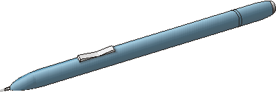
Application Toolbox Use of a Pen The primary tool of our prototype application is a pen with a functionality that depend on the actual task. Our pen has a rocker switch with two positions like the on the figure below.
Traditional UI Elements An ideal user-interface of a sketch-based system has a lot of working real estate. However, for certain operations it is necessary to introduce graphical elements, such as buttons, toolbars, or menus, because there is no easy way to communicate otherwise with the system. This may change, thought, when verbal interaction is introduced. For our prototype we have tried to keep the working area uncluttered and to avoid a large number and a frequent use of graphical user-interface elements. Hence, to draw a typical sketch it is only once necessary to press a button, which is when the user has finished his or her sketch and wants to tell the system that the sketch is completed and the database query can be initiated. Alternative UI Elements The major goal of alternative user-interface elements is to enhance the interface between user and computer and support an interaction without being obtrusive (Blaser, Sester, Egenhofer 1999). A promising approach for doing this is to copy from frequently used methods that people use to communicate with each other. For a sketch-based application this implies that we have to take drawing gestures into account. Our prototype has three typical drawing gestures implemented that could be used for any drawing application. |
||
| Delete Gesture | ||
|
The delete gesture is used to eliminate a previously drawn object from the sketch and to put its elements (strokes) onto the drawing stack. The gesture consists of two crossing strokes that intersect at an angle of around 90°. The affected sketch object is determined based on the gesture’s location and on a temporal factor. That is, if more than one object are candidates for a deletion, then only the most recently drawn object gets eliminated. The figure below shows an example of a situation where a user deletes an unwanted house.
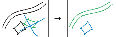
Example of a delete gesture applied on a drawn object in a sketch. |
||
| Intuitive pan and zoom | ||
|
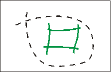
Our approach for the zoom operation is an alternative to the standard method that zooms to the area that is selected within a box. By making movements towards the center of the drawing area our tool zooms gradually out and by making the converse movement the tool can be used to zoom in. This gesture is founded on people’s behavior when they search for something (dig or excavation gesture) or if they want to hide something (cover or conceal gesture)
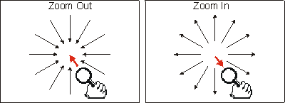
Principle of the zoom gesture: Zooming out (left image) and zooming in (right image). |
||
| Lasso selection, encircle | ||
|
There are two bag selection modes implemented into the prototype. The first method is the common approach to select all entities within a box, the second approach is less constrained as it lets the user freely specify the shape of the selection area. If an entire object falls into the area then this object is selected as a whole, if only some strokes are within the boundaries then only those strokes are selected. When the selection area overlaps or contains more than one object, only entire objects are selected.
The user has drawn a bag around an object that will be selected as a whole.Because objects, strokes, or groups of them can also be selected by simply pointing at them, the user gets a lot of flexibility how he or she wants to select entities for further processing without having to change the tool.
|
||
|
Visual Clues The communication from computer to user is primarily conducted on a visual base. Although is possible—and for some applications even adequate—to give acoustical feedback and instructions, it is often considered distracting or unwanted, for instance when more than one user is working in the same environment. Sound can only hardly be channeled into a specific direction, it is transitory, and people are not capable to interpret more than one or two acoustical signals at the same time. This is much different with the visual approach that can be directed and that provides the base for a broadband interaction between user and system, which is, because the output device can be scanned and because it is perpetual. We have, therefore, implemented various visual clues and forms of interaction that people already are familiar with in their everyday life. |
||
| Use of colors | ||
|
If used appropriately, colors are a very powerful tool to convey information [Imhof, 1982 #1735]. In our prototype colors are used to inform the user about the current status of the sketch and its objects. Over time an sketched object can, therefore, take different colors. At the beginning each object is blue, a color which signifies the current object. The object keeps this color until the first stroke of the next object—the new current object—has been detected, at which point it changes its color to green, marking it as the previous object. Finally, when yet another object is drawn the object’s color turns to black, the consolidated color. Other object or stroke colors are purple for detected text objects and light blue for selected strokes within a selected object. Using this approach, a user stays informed during the entire process of sketching that is, he or she knows what strokes have been grouped to objects and how objects have been interpreted. The readiness of the sketch, finally, is indicated by three lights with different colors (red, yellow, green, and blue) that are situated in the lower right corner of the user-interface. The lights indicate the status of sketched objects, the formal network, and the spatial database query (provided but not yet functional). |
||
| Guiding cursor icons | ||
|
To indicate the tool that is currently selected we use a number of self-explanatory icons for the pen or mouse cursor. This technique is being used by a host of modern applications and its concept has proved to be very efficient and intuitive. The figure below shows the set of cursor icons used within the prototype, according to their importance.

Cursor icons used within the prototype. Indicated functionality of the tools from left to right: Sketch, select, grab, zoom, pan, explicit handwriting, and typing. |
||
| Using shadows | ||
| The use of shadows for objects or strokes that are being moved is a practical and visual method to help users during the process of sketch editing. The shadow is a light gray pendent of the object or stroke at its original location before it was moved. Such, the user can check out the new placement while still having the reference of the previous one. | ||
|
[Sketching Survey] [Prototype] [Publications] [People & Organizations] [Related Topics]
|
||
|
||