
|
||
|
Levels of Abstraction Our prototype has three different levels of abstraction for the same data. In Microsoft MFC terminology different levels of abstraction are called Views. The primary data view is the Sketch View, this is the place where the sketch is generated and edited and this is also the only mandatory view. The other two views can be used to examine the intermediate results of the sketch interpretation.
|
|
|
|
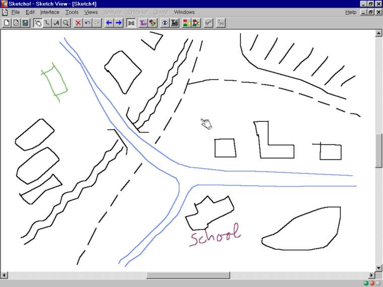
Sketch View This is the normal environment of the user interface, it is the place where the sketch is initially created, edited, and from where a spatial query can be made. The user Interface is very simple, including only few primary drawing tools (draw, select, zoom, delete) and even somebody with only limited computer experience can readily draw a simple sketch---It worked fine with my four and six year old child---. If the mouse as input device is substituted with an electronic pen and used in conjunction with a tablet or directly on a flat screen, then the usability and simplicity is further enhanced. In our experiments we have used a Wacom 12x12" drawing tablet and a pen with a double switch button (rocker switch). One button is configured to invoke extended functions of the pen and the other to get context information or set object properties, depending on the actual cursor position.
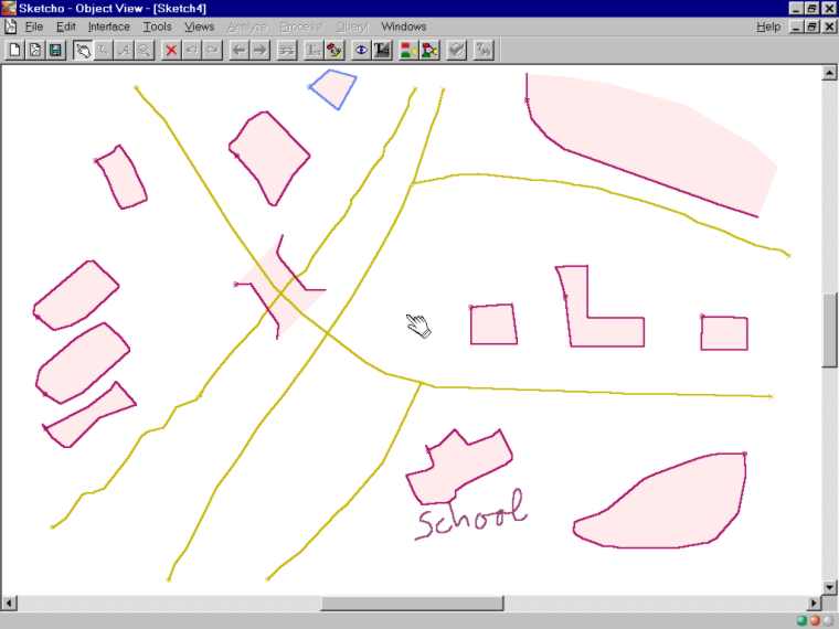
Object View The Object View shows what the application has detected in point of view objects. The view shows a simplified and interpreted outline of each object and it conveys---using different colors---each object’s type. Should an object have been misinterpreted, for instance a region has been considered a line because it was not automatically closed, then this can be reversed by a simple push of a button. It is also possible to move, delete, and edit objects at this stage, all without changing the initial sketch. That is, modifications on this level are only passed forwards to the next level of abstraction, but not backwards.
Formal View The Formal View is the third and last view of our prototype application. This view represents the highest level of abstraction where every object or relation is solely depict by a symbol that is connected to other entities according the previous sketch analysis. Currently there are four different symbols implemented. These symbols cover the present data model of the prototype, which are: region and line objects, and binary and multiple relations. As mentioned before, multiple relations can be established, but they do net yet carry any data, but that necessary for the connection of the selected objects. Despite the relative simple and abstract look of this view, the user has some powerful tools to further edit the sketch in this phase. For instance, it is possible to disable or re-enable relations or objects, and it is as well possible to create new relations between objects even if there is no previous automatically generated relation.
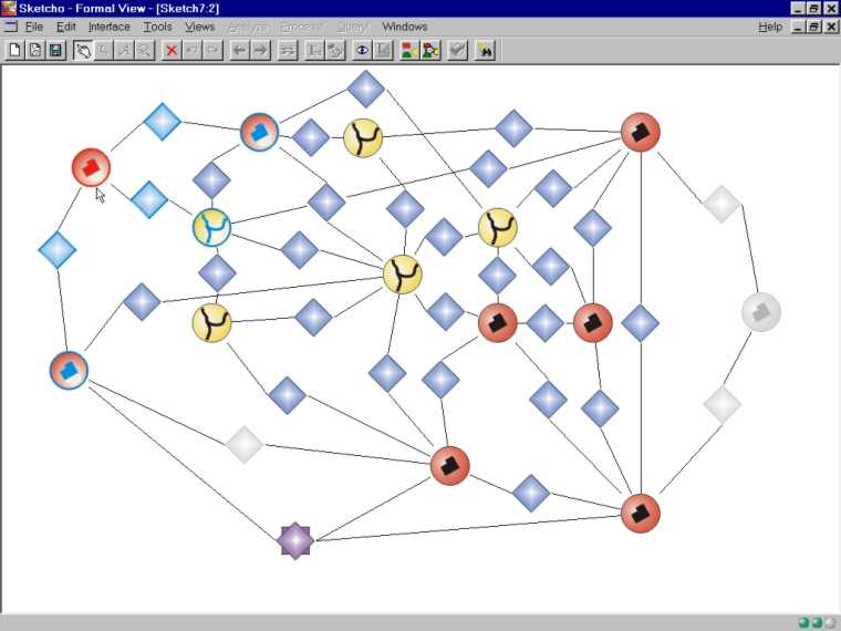
The figure above shows a subset of all relations that are obtained when the original sketch in this example is processed. We have deleted some relations (no direct connection between objects) and disabled some others (grayed relation icon). The purple double diamond signifies a multiple relation that was added manually to the representation (e.g. all three buildings belong to the same district). The changes were made in order to demonstrate the capabilities of the Formal View and to obtain a clearer, simpler representation.
|
||
|
[Sketching Survey] [Prototype] [Publications] [People & Organizations] [Related Topics]
|
||
|
||