SQbS - Prototype Application
Sketch Processing

A sketch is processed essentially in three steps. The first step is concerned about parsing the input stream of points and about associating strokes with objects. The second step focuses on processing and classifying raw objects, and the third step, finally, connects detected objects with each other.

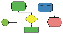
Flow Chart
Sketch Parsing

The objective of this first processing step is to check the quality of the user input and to simplify and refine obtained information. The user input is recorded in form of lists of connected points (strokes). The algorithms used during this process reduce the number of points while retaining the original shape of the stroke. Hence, duplicate or other redundant points are eliminated. This simplification process is immediately followed by a first evaluation of the stroke and an attempt to associate the stroke with a previously drawn object. That is, we check for every newly drawn stroke if it can be associated to a previously drawn object or if it can be considered as the first stroke of a new object.

Object Extraction

Once an object is complete that is, whenever the most recent stroke has been considered to be the first stroke of a new object, then this raw (previous) object is analyzed and further classified. This consolidating process consists of a number of steps.

    • Text Extraction
    • Gesture Extraction
    • Segmentation
    • Object Completion
    • Outline Extraction
    • Type Determination
    • Parallel Extraction
    • Kernel Extraction

The first step is to distinguish text from other objects. Objects that have been considered to be text are excluded from further interpretation processes and are linked as written annotations to the most likely object in the vicinity. The current version of the prototype has no actual handwriting recognition implemented.

Sketched Text

People use drawn gestures to communicate or initiate a certain message or action. In this sense they are not real objects, because they can be purged once they have been interpreted and executed. Many gestures are personal, but there is also a set of drawn gestures that is frequently used in sketches. Our prototype understands two commonly used gestures for geo-spatial sketches: dashed lines and hatched areas.

Gesture Detection 1

There are many other important gestures, such as the delete gesture (e.g. crossing out an object) or the scribble gesture to fill or mark an object. A real world application would have to take a standard set of gestures into account, must be trainable, and capable to learn new gestures that are stored in user-profiles.

Gesture Detection 2

The process of segmentation is fundamental for all subsequent processing tasks. Here the "unintelligent" strokes are converted into "intelligent" sketch elements (segments) that have no intersections between start and end point and that have knowledge of neighboring elements. Such, a segment can be closed, self-closed, half-open, or it can be completely open. In the example four initial strokes are converted into twelve segments.

Segmentation

Sketching is no exact science and people often sketch their objects incompletely and inaccurately. This leads to gaps and irregularities in objects that are difficult to process if they are not previously corrected. People, on the other hand, have no problems recognizing even very incomplete figures, because they can anticipate the correct shape or silhouette solely based on a few fragmentary strokes as is shown in the Figure below.

Object Completion

Although this example is somewhat exaggerated, gaps and incomplete objects are very common. In most cases strokes do not exactly intersect where they are meant to and such they stop before they can intersect another stroke or "overshoot". The prototype covers three of the most common cases, to correct these problems (See figure below).

Object Completion

The subsequent object clean-up is simply the process of dropping segments that are very short and partially connected or fully open. This is often the case when two strokes intersect and one or both resulting segments.

The next step is to extract outlines. For this purpose the application tries to find the largest closed area of the object. If there are more than one area then they are all stored in a sorted list, depending their size. If there is no closed area then the convex hull is calculated and stored as a quasi area. The prototype supports multiple areas that can contain each other. The only restriction is that closed regions may not touch, in which case solely one region (the larger one) is stored.
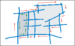
Outline Generation

The principle of outline extraction is to follow segments and to turn always to towards the same side at intersections, where more than two segments come together. This procedure has to be done at least twice for each object, because it is very difficult to predict the appropriate turning direction a priori. The results are two areas that may differ in their size (Figure above). The bigger size is the outline. This procedure is repeated until all segments are processed, that is until there are no closed segments left that have not yet been processed.

The type of an object is determined by comparing the sum of areas of all region of the object with the area of the convex hull of the object. If the sum is smaller than a certain percentage, then the object is considered a line object - even if there are regions in the object. Using this approach, we can also have mixed type objects that is, objects that contain more than just one element type. If the system should misinterpret an object, then the user can change the type of an object by the push of a button.

If an object has been considered being a line, then the application tries to find parallels within the object. For this purpose we check for every segment if there are neighboring segments that do not belong to the same stroke but that are in reach and parallel to this one. If parallels are found we check if there are other parallels within the same object that are potential meet candidates. The figure below shows an example of a road intersection where such a procedure is useful.

Parallel Extraction

Detected parallels substitute all segments that have been involved in their extraction. These parallels and the remaining segments are stored in a list of lines within the object. This list of lines is sorted depending on the length of each line.

For region objects we define the kernel as the longer centerline of the tilted minimum bounding rectangle (TMBR) of an object. This is an abstraction for the real centerline of an object that is more complex to calculate. The TMBR is that bounding rectangle that has the smallest possible area of the whole set of bounding rectangles for a specific object. Such a bounding rectangle is obtained - with adequate accuracy - by rotating an object with small increments (e.g. 1.0° grad in our prototype) and recording size and position of all MBR’s. The advantage of a TMBR is that it is only slightly more complex than a regular MBR but has, compared with this one a directional component and an optimal fit for a specific object. Furthermore, most objects in sketches are boxes anyway, and such a TMBR is an ideal approximation for many calculations.
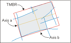
Tilted Minimum Bounding Rectangle

Levels of Abstraction


[Home] [Concept] [Potential Applications] [Spatial Theory] [User Interface]
[Sketching Survey] [Prototype] [Publications] [People & Organizations] [Related Topics]

© by abl / Last updated 4/6/99